Row
 left click
Rows arrange copies of Lands Design elements or other objects along a curve.
Insert a row
After running the laRow command, the Row insert dialog box will appear. This dialog shows the basic options of the Row object in two different tabs:
Steps:
- Select a row element under the Sample tab. This element can be specified in three different ways:
 A block from the Block Library.
 A file from your PC.
 An existing object in the model.
- Select the Row parameters under the Row tab. Click OK to close the dialog.
- Pick an existing curve in the model to define the row, or select a different option in the command line.
- Polyline: the row will be created as if you were drawing a polyline.
- Spline: the row will be created as if you were drawing a spline.
- Circle: the row will be created as if you were drawing a circle. The first click determines the center of the circle, and the second click determines the Radius.
- Arc: the row will be created as if you were drawing an arc. The first click determines the insert point. The second click determines a middle point in the arc. The third and last click determines where the arc ends.
- Rectangle: the row will be created as if you were drawing a rectangle. The first click determines one corner of the rectangle, and the second click determines the opposite corner.
- Press ENTER, ESC, or right-click to end the command.
The row parameters can be edited while they are being inserted and after finishing the command, from the Lands Design Edit Panel, in the Properties section, under the Row tab.
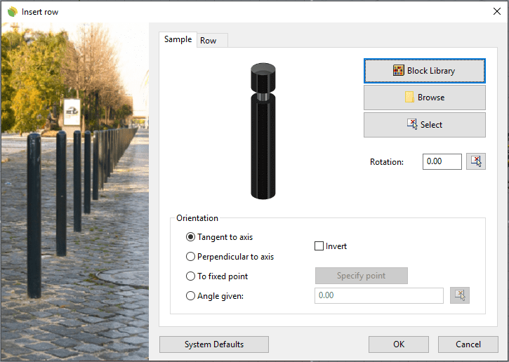
Insert dialog box for the Row object
NoteThe row sample can be anything but a plant. To create plant rows, use the laPlantRow command.
Control points 
Rows have the same control points as the curves used to generate them, regardless of the number of element items or their position.
In addition, they have a Move control arrow, to move the whole object.
Row control points are automatically enabled when selecting rows one by one. To turn one ore more Row object control points on, just select them and run the PointsOn command (or press F10). To turn the points off, press the Esc button or run the PointsOff command.
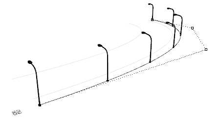
Control points on rows
Insert options and parameters
The row insert options and parameters are divided in different tabs, and are available from different dialogs:
- Row insert dialog box (only available when inserting new rows).
- Row properties section, in the Lands Design Edit panel.
- Object Properties dialog.
- Properties Explorer dialog.
General
General attributes for the row object: Name, Color, Layer, and Transparency (only visible in Conceptual display mode).
Sample
Parameters for the row items:
- Sample: row element. You can either select it from the Block Library, from your PC or pick an existing object in the model.
- Rotation: angle of rotation of each element from its own insert point.
- Orientation: there are four options available to orient the row element in relation with the row axis curve:
- Tangent to axis
- Perpendicular to axis
- To fixed point: click on the Specify point button to pick a point in the model
- Angle given
When rows have more than one sample, the parameters of each one are available after selecting the desired sample from the Object Selection List in the Lands Edit panel
Row
There are two options to distribute elements in rows:
- Number of units: sets the total number of row items along the row axis curve.
- Separation: places the row items at a certain distance among them, according to an alignment on the row axis curve (at the beginning, centered or at the end).
- Distance to axis: moves the position of elements across the path curve.
Rows can combine different element samples:
- # of elements: type the number of different samples. The list of different samples will appear in the Object Selection List in the Lands Edit panel, from where they can be selected to edit their parameters.
- Distribution: options to distribute the row elements when there is more than one sample type.
Inserted units: displays the exact number of element units in the row.
Material
This tab lets you change the textured image assigned to this element and define the image size and reflectivity.
Edit options
These are the edit options for the Row object, available in the Edit area of the Edit panel:
 Update
 Convert to 2D. Displays the object in 2D display.
 Convert to 3D. Displays the object in 3D display.
- Show 2D and 3D: Turns the object 2D and 3D display on simultaneously.
- Copy properties from another object
- Copy to another curve
- Invert curve
- Extract curve
- Adjust
- Don't adjust to terrain
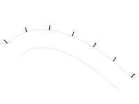
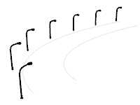
Row graphical display
Row object offers a simultaneous 2D and 3D display on the drawing, depending on the entity selected. If the row entity is chosen from the Block Library, it offers a 2D and 3D display. If the entity is picked from the model, it will only have a 3D display.
|
|
| 2D | 3D |