Path
 left click
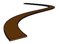
A path in Lands Design is an extruded profile along an axis.
Insert a Path
After running the laPath command, the Path insert dialog box will appear. This dialog shows the basic options of the Path object in two tabs.
Steps:
- Select the path Section profile. There are two options available:
- Rectangular: define the rectangular profile dimensions. Use the Pick button
 to measure the dimensions in the model.
 - Custom: choose the Select button to pick a curve in the model, or the Draw button to create the new profile in the model as a polyline.
- Rectangular: define the rectangular profile dimensions. Use the Pick button
- Select the rest of Path parameters. Click OK to close the dialog.
- Pick an existing curve in the model to create the path, or select a different option in the command line.
- Polyline: the path will be created as if you were drawing a polyline.
- Spline: the path will be created as if you were drawing a spline.
- Circle: the path will be created as if you were drawing a circle. The first click determines the Center of the Circle, and the second click the Radius.
- Arc: the path will be created as if you were drawing an arc. The first click determines the insert point. Second click determines a middle point in the arc. Third and last click determines where the arc ends.
- Rectangle: the path will be created as if you were drawing a rectangle. The first click determines one corner of the rectangle and the second click determines the opposite corner.
- Press ENTER, ESC or right click to end the command.
NoteMake sure the curve selected as the path section profile is aligned with the XY axis.
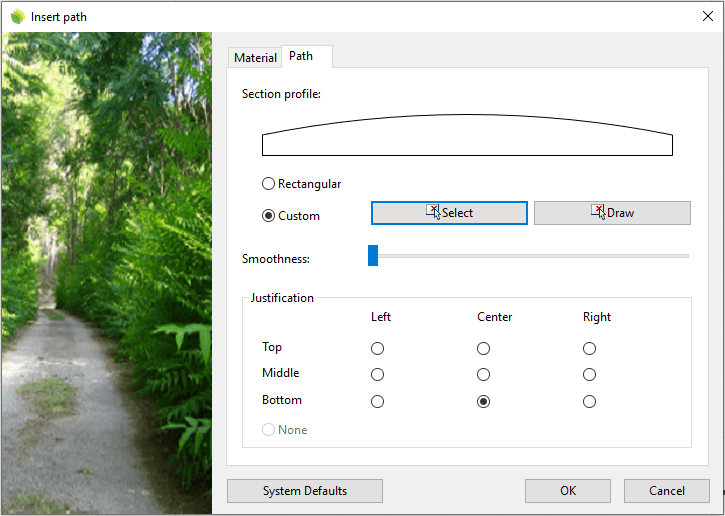
Insert dialog box for the Path object
Control Points 
Path objects have three different types of control points:
- Path axis Control points: they are the same control points as those from the curves used to generate the paths.
- Move control arrow: Arrow located at the beginning of the path object, which is used to move the whole object.
- Section profile Control points: These control points are used to modify the path section profile. They are the same control points than those from the curves used to define the path section profile. They are located at the beginning of the path object.
Path control points are automatically enabled when selecting paths one by one. To turn one ore more Path object control points on just select the paths and run the PointsOn command (or press F10). To turn the points off, press ESC button or run the PointsOff command.
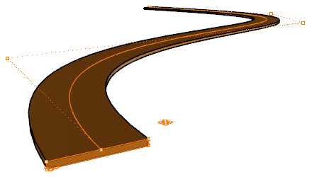
Control points on Path objects
Insert Options and Parameters
The Path object insert options and parameters are divided in different tabs, and are available from different dialogs:
- Path insert dialog box (only available when inserting new Paths).
- Path properties section, in the Lands Design Edit Panel.
- Object Properties dialog.
- Properties Explorer dialog.
General
General attributes for the Path object: Name, Color, Layer, and Transparency (only visible in Conceptual display mode).
Path
- Section profile: curve used to define the Path section profile.
- Smoothness: precision in which the path object is subdivided along the axis curve in order to fit with its path. This parameter is only relevant when the Path object has been created from a curved curve.
- Justification: it marks the position of the path section profile from which it is extruded along the path axis curve. There are nine possible justifications. The None justification maintains the path alignment along the path axis, even though you modify the path section profile.
Material
This tab lets you change the textured image assigned to this element and define the image size and reflectivity.
Edit options
These are the edit options for the Path object, available in the Edit area of the Edit Panel:
 Update
 Convert to 2D. Displays the object in 2D representation.
 Convert to 3D. Displays the object in 3D representation.
- Show 2D and 3D: Turns the object 2D and 3D representation on simultaneously.
- Copy properties from another object
- Copy to another curve
- Invert curve
- Extract curve
- Adjust
- Don't adjust to terrain
- Path
- Edit section profile: this command places a construction plane aligned with the path section profile at the start of the object. It makes it easier to edit the path profile through its control points. Run the CPlane command (and select World > Top) from the command line, to restore the position of the Construction plane.
Path graphical display
Path object offers a simultaneous 2D and 3D display on the drawing.
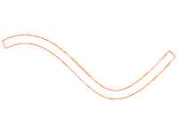
|
|
| 2D | 3D |